What is Torque
Torque is any force or system of forces that tends to cause rotation about an axis.
Measurement of Torque
Imagine someone tightening a bolt using a socket attached to a meter (m) long bar. If they apply 10 kg of force (kgf) perpendicular to the bar they will produce a torque of 10 kgf·m at the axis (the centre of the bolt).
However, under the S.I. system of measurement, force is expressed in Newtons (N) rather than kgf. The conversion between kgf and N is x 9.807 so the person is applying 98.07 N·m of torque.

The Importance of Torque Control
Although many methods exist to join two or more parts together, the ease of assembly and disassembly provided by threaded fasteners make them the ideal choice for many applications.
The object of a threaded fastener is to clamp parts together with a tension greater than the external forces tending to separate them. The bolt then remains under constant stress and is immune from fatigue. However, if the initial tension is too low, varying loads act on the bolt and it will quickly fail. If the initial tension is too high, the tightening process may cause bolt failure. Reliability therefore depends upon correct initial tension. The most practical way of ensuring this is by specifying and controlling the tightening torque.
Bolt Tension
When an assembly is clamped by tightening a nut and bolt, the induced tension causes the bolt to stretch. An equal force acts to compress the parts which are thus clamped.
The proof load of a bolt, normally established by test, is the load which just starts to induce permanent set – also known as the yield point. Typically, bolts are tightened to between 75% and 90% of yield.

Friction in the Bolted Joint
When a threaded fastener is tightened, the induced tension results in friction under the head of the bolt and in the threads. It is generally accepted that as much as 50% of the applied torque is expended in overcoming friction between the bolt head and the abutting surface and another 30% to 40% is lost to friction in the threads. As little as 10% of the applied torque results in useful work to tension the bolt.

Given that up to 90% of the applied torque will be lost to friction, it follows that any changes in the coefficient of friction resulting from differences in surface finish, surface condition and lubrication can have a dramatic effect on the torque versus tension relationship. Some general points can be made:
Most torque tightened joints do not use washers because their use can result in relative motion between the nut and washer or the washer and joint surface during tightening. This has the effect of changing the friction radius and hence affects the torque-tension relationship. Where a larger bearing face is required then flange nuts or bolts can be used. If washers are to be used, hard washers with a good fit to the shank of the bolt give lower and more consistent friction and are generally to be preferred.
Degreasing fasteners of the film of oil usually present on them as supplied will decrease the tension for a given torque and may result in shear of the fastener before the desired tension is achieved.
Super lubricants formulated from graphite, molybdenum disulphide and waxes result in minimal friction. Unless allowance is made in the specified tightening torque, the induced tension may be excessive causing the bolt to yield and fail. However, used in a controlled manner, these lubricants serve a useful purpose in reducing the torque to produce the desired tension meaning that a lower capacity tightening tool can be used.
For reasons of appearance or corrosion resistance, fasteners may be plated. These treatments affect the coefficient of friction and therefore the torque versus tension relationship.
Friction is often deliberately introduced into the fastener to reduce the possibility of loosening due to vibration. Devices such as lock-nuts must be taken into account when establishing the correct tightening torque.
As a rough guide, the calculated tightening torque should be multiplied by the factor from the table below according to surface treatment and lubrication.
|
|
Surface Condition of Bolt
|
|
Untreated
|
Zinc
|
Cadmium
|
Phosphate
|
|
Surface Condition of Nut
|
Untreated
|
1.00
|
1.00
|
0.80
|
0.90
|
|
Zinc
|
1.15
|
1.20
|
1.35
|
1.15
|
|
Cadmium
|
0.85
|
0.90
|
1.20
|
1.00
|
|
Phosphate and oil
|
0.70
|
0.65
|
0.70
|
0.75
|
|
Zinc with wax
|
0.60
|
0.55
|
0.65
|
0.55
|
When a threaded fastener is tightened, the induced tension results in friction under the head of the bolt and in the threads. It is generally accepted that as much as 50% of the applied torque is expended in overcoming friction between the bolt head and the abutting surface and another 30% to 40% is lost to friction in the threads. As little as 10% of the applied torque results in useful work to tension the bolt.
Tightening to Yield
Bolts tightened to yield provide consistently higher preloads from smaller diameter bolts. The reduced fastener stiffness reduces the fatigue loading to which the bolt is subjected under repeated external load reversals, e.g. cylinder heads and connecting rods.
In theory, a bolt tightened to its yield point will provide the strongest and most fatigue-resistant joint possible, within the physical limitations of the bolt material and manufacturing process.
The downside of this method is the cost of the sophisticated equipment necessary to determine when the bolt goes into yield.
Torque Tension Calculator
For further information and guidance on establishing the correct tightening torque for a fastener, see Norbar’s web based calculator

When Torque Doesn't Equal Tight
As we have established, it is the tension in a fastener rather than the torque that is the critical factor. Torque is an indirect means of establishing tension and in a correctly engineered joint and with a controlled tightening process, it is a satisfactory method under the majority of circumstances.
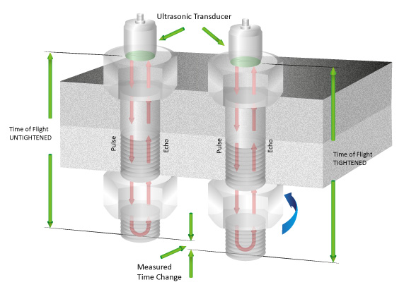
However, in joints that are highly critical due to safety or the cost and implications of machine down-time, a more direct means of establishing tension is needed. Various methods exist including several types of load indicating bolts or washers. However, one of the most versatile methods is to measure the extension of the bolt due to the tightening process using ultrasound and this is exactly what Norbar’s USM-3 does.
Recommended Maximum Torque Values
The information supplied here is intended to be an acceptable guide for normal conditions. For critical applications, further information and research will be necessary. The following basic assumptions have been made:
a. Bolts are new, standard finish, uncoated and not lubricated (other than the normal protective oil film)
b. The load will be 90% of the bolt yield strength
c. The coefficient of friction is 0.14
d. The final tightening sequence is achieved smoothly and slowly
If lubrication is to be applied to the nut/bolt, multiply the recommended torque by the appropriate factor shown in the table above ‘Surface Condition’. Alternatively, use the Torque/Tension Calculator which enables fastener and friction conditions to be modified with ease.
|
M
|
BOLT GRADE |

mm
|
| 3.6 |
4.6 |
5.6 |
5.8 |
6.8 |
8.8 |
9.8 |
10.9 |
12.9 |
| Torque in N·m |
| M 1.6 |
0.05 |
0.07 |
0.09 |
0.11 |
0.14 |
0.18 |
0.21 |
0.26 |
0.31 |
3.2 |
| M 2 |
0.11 |
0.14 |
0.18 |
0.24 |
0.28 |
0.38 |
0.42 |
0.53 |
0.63 |
4 |
| M 2.5 |
0.22 |
0.29 |
0.36 |
0.48 |
0.58 |
0.78 |
0.87 |
1.09 |
1.31 |
5 |
| M 3 |
0.38 |
0.51 |
0.63 |
0.84 |
1.01 |
1.35 |
1.52 |
1.9 |
2.27 |
5.5 |
| M 4 |
0.71 |
0.95 |
1.19 |
1.59 |
1.91 |
2.54 |
2.86 |
3.57 |
4.29 |
7 |
| M 5 |
1.71 |
2.28 |
2.85 |
3.8 |
4.56 |
6.09 |
6.85 |
8.56 |
10.3 |
8 |
| M 6 |
2.94 |
3.92 |
4.91 |
6.54 |
7.85 |
10.5 |
11.8 |
14.7 |
17.7 |
10 |
| M 8 |
7.11 |
9.48 |
11.9 |
15.8 |
19 |
25.3 |
28.4 |
35.5 |
42.7 |
13 |
| M 10 |
14.3 |
19.1 |
23.8 |
31.8 |
38.1 |
50.8 |
57.2 |
71.5 |
85.8 |
17 |
| M 12 |
24.4 |
32.6 |
40.7 |
54.3 |
65.1 |
86.9 |
97.9 |
122 |
147 |
19 |
| M 14 |
39 |
52 |
65 |
86.6 |
104 |
139 |
156 |
195 |
234 |
22 |
| M 16 |
59.9 |
79.9 |
99.8 |
133 |
160 |
213 |
240 |
299 |
359 |
24 |
| M 18 |
82.5 |
110 |
138 |
183 |
220 |
293 |
330 |
413 |
495 |
27 |
| M 20 |
117 |
156 |
195 |
260 |
312 |
416 |
468 |
585 |
702 |
30 |
| M 22 |
158 |
211 |
264 |
352 |
422 |
563 |
634 |
792 |
950 |
32 |
| M 24 |
202 |
270 |
337 |
449 |
539 |
719 |
809 |
1,011 |
1,213 |
36 |
| M 27 |
298 |
398 |
497 |
663 |
795 |
1,060 |
1,193 |
1,491 |
1,789 |
41 |
| M 30 |
405 |
540 |
675 |
900 |
1,080 |
1,440 |
1,620 |
2,025 |
2,430 |
46 |
| M 33 |
550 |
734 |
917 |
1,223 |
1,467 |
1,956 |
2,201 |
2,751 |
3,301 |
50 |
| M 36 |
708 |
944 |
1,180 |
1,573 |
1,888 |
2,517 |
2,832 |
3,540 |
4,248 |
55 |
| M 39 |
919 |
1,226 |
1,532 |
2,043 |
2,452 |
3,269 |
3,678 |
4,597 |
5,517 |
60 |
| M 42 |
1,139 |
1,518 |
1,898 |
2,530 |
3,036 |
4,049 |
4,555 |
5,693 |
6,832 |
65 |
| M 45 |
1,425 |
1,900 |
2,375 |
3,167 |
3,800 |
5,067 |
5,701 |
7,126 |
8,551 |
70 |
| M 48 |
1,716 |
2,288 |
2,860 |
3,813 |
4,576 |
6,101 |
6,864 |
8,580 |
10,296 |
75 |
| M 52 |
2,210 |
2,947 |
3,684 |
4,912 |
5,895 |
7,859 |
8,842 |
11,052 |
13,263 |
80 |
| M 56 |
2,737 |
3,650 |
4,562 |
6,083 |
7,300 |
9,733 |
10,950 |
13,687 |
16,425 |
85 |
| M 60 |
3,404 |
4,538 |
5,673 |
7,564 |
9,076 |
12,102 |
13,614 |
17,018 |
20,422 |
90 |
| M 64 |
4,100 |
5,466 |
6,833 |
9,110 |
10,932 |
14,576 |
16,398 |
20,498 |
24,597 |
95 |
| M 68 |
4,963 |
6,617 |
8,271 |
11,029 |
13,234 |
17,646 |
19,851 |
24,814 |
29,777 |
100 |
Torque Conversion Factors
The below formulas and information provide guidance on different conversion factors e.g. the effect of torque wrench extensions.
|
|
S.I. Units
|
Imperial Units
|
Metric Units
|
|
cN·m
|
N·m
|
ozf·in
|
lbf·in
|
lbf·ft
|
kgf·cm
|
kgf·m
|
|
Units to be Converted
|
1 cN·m =
|
1
|
0.01
|
1.416
|
0.088
|
0.007
|
0.102
|
0.001
|
|
1 N·m =
|
100
|
1
|
141.6
|
8.851
|
0.738
|
10.20
|
0.102
|
|
1 ozf·in =
|
0.706
|
0.007
|
1
|
0.0625
|
0.005
|
0.072
|
0.0007
|
|
1 lbf·in =
|
11.3
|
0.113
|
16
|
1
|
0.083
|
1.152
|
0.0115
|
|
1 lbf·ft =
|
135.6
|
1.356
|
192
|
12
|
1
|
13.83
|
0.138
|
|
1 kgf·cm =
|
9.807
|
0.098
|
13.89
|
0.868
|
0.072
|
1
|
0.001
|
|
1 kgf·m =
|
980.7
|
9.807
|
1389
|
86.8
|
7.233
|
100
|
1
|
Formulae
Accepted formulae relating torque and tension, based on many tests are: -
For Imperial Sizes
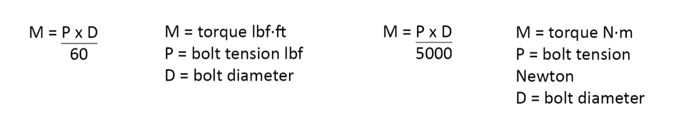
These formulae may be used for bolts outside the range of the tables.
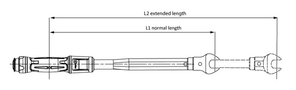
Formula for Calculating the Effect of Torque Wrench Extensions
M1 = M2 x L1/L2
Where L1 is the normal length and L2 is the extended length, M1 is the set torque and M2 the actual torque applied to the nut.
Example
The required torque on the fastener is 130 N·m (M2) but what do you set on the torque wrench scale?
L1 = 500 L2 = 650
(units of length not important, this is ratio)
M1 = 130 x 500/650
M1 = 100
Recommended Calibration Period of Torque Wrenches
The calibration integrity of torque wrenches depends largely upon the use and environment to which the tool is subjected. In test conditions, the torque wrench should remain within the tolerances laid down by BS EN ISO 6789:2017 for at least 5,000 cycles. In practice, this may be reduced by ingress of dust, causing wear; or by damage caused by using the tool to loosen fasteners or being dropped regularly. Assuming your operators to be trained in the use of torque wrenches, and provided the comments in our instruction leaflet are followed, a period of twelve months is reasonable for torque wrenches used in non-safety critical applications, a three month or even monthly check would be advisable.
We cannot be responsible for the selection of a calibration interval, but hopefully the above information is of assistance.